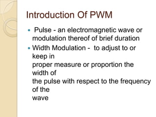
Understanding The Pulse Width Modulation Used In A Variable Speed Dc Motor Control Of Usg Pptx
Master pwm motor control techniques for precise dc motor speed regulation A series of pwm related application notes including measurement approach and a guide to measuring efficiency of the various stages in a pwm motor drive will be discussed in future application notes. Learn pulse width modulation principles, circuits, arduino implementation, and practical applications with examples.
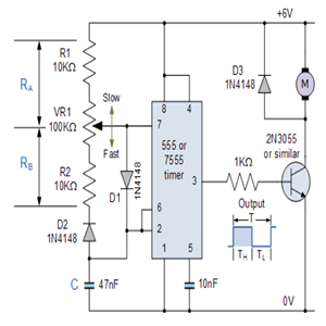
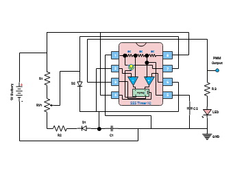
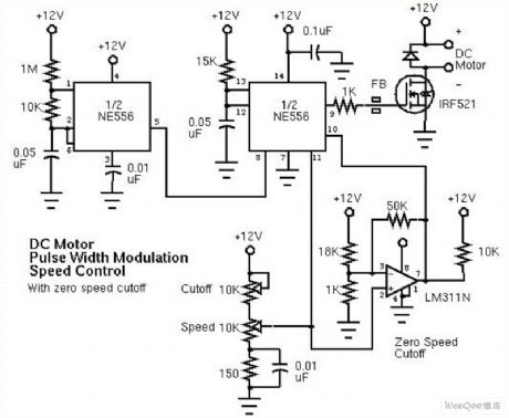
Pulse Width Modulation Circuit - Circuit Diagram
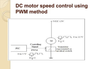
Pulse width modulation can control the speed of dc motors there are many different ways to control the rotational speed of dc motors but one very simple and easy way is to use pulse width modulation, or pwm This application note was an introduction to pulse width modulation theory But before we start looking at the in's and out's of pulse width modulation we need to understand a little more about how a dc motor works
Next to stepper motors, the permanent.
Pulse width modulation (pwm) is a powerful technique for controlling the speed and torque of dc motors in a wide range of industrial applications By varying the duty cycle of a square wave signal, pwm allows for precise control over the average voltage supplied to the motor, enabling efficient and reliable operation. Understanding the basics of pulse width modulation (pwm) power delivered to devices can be changed by raising or lowering the voltage and current But this method does not always produce intended results
Pulse width modulation (or pwm) can be used to better control variable loads. Learn how to control motor speed using pwm This guide covers setup, duty cycles, components, and troubleshooting for smooth, efficient motor control. A simple example is using pulse width modulation to control the speed of an electric motor
For this example, consider an electric motor specified to operate at a maximum speed of 3,000 rpm at 12 volts dc
The chart below represents the angular velocity and average voltage as a function of pwm duty cycle: By adjusting the width of the pulses in a signal, pwm allows for efficient control of motor performance, delivering precise regulation of motor speed and torque Additionally, it plays a crucial role in power. We look at the operation of pulse width modulators and why pwm are preferred over linear amplifiers in speed control of dc motors.
This tutorial will discuss timer peripheral modules, dc motors, motor controllers, and configuration of your chip to output a pwm or pulse width modulated signal The first section of this this tutorial provides the basics of dc (direct current) motors The electronic circuits created to control the. What is pulse width modulation

Pwm is particularly helpful for effectively regulating the output of audio amplifiers, the speed of motors, and the brightness of light
They are frequently used in microcontrollers. While all variable frequency drives (vfds) control the speed of an ac induction motor by varying the motor's supplied voltage and frequency of power, they all do not use the same designs in doing so There are three major vfd designs commonly used today Pulse width modulation (pwm), current source inverter (csi), and voltage source inverter (vsi).
Power delivered to devices can be changed by raising or lowering the voltage and current Pulse width modulation (or pwm) can be used to better control variable loads Load devices are designed to run efficiently and perform their respective tasks when provided with a certain voltage, consuming a. Pwm works by varying the width of pulses in a signal to regulate the amount of power delivered to a load, allowing for precise control over devices such as motors, lights, and amplifiers
This video provides a short technical introduction to pulse width modulation, some of the most common applications of pulse width modulation, and how pulse width modulation is measured and analyzed.
It is a technique used in electronics to encode analog information in form of duty cycle of periodic pulses It is a common technique used to control the power delivered to electronic devices Most common applications are motor speed control. The corliss steam engine was patented in 1849
A centrifugal governor was used to provide automatic feedback Some machines (such as a sewing machine motor) require partial or variable power In the past, control (such as in a sewing machine's foot pedal) was implemented by use of a rheostat connected in. Heed some basic physical phenomena to avoid unexpected performance issues, along with general guidelines for using a pwm driver with a brushless dc motor
Pwm stands for pulse width modulation, a technique used to control the amount of power delivered to electrical devices
It is widely used in electronics, especially when dealing with motors, leds, and audio signals. Pwm, or pulse width modulation, aside from being the preferred method for controlling led lighting, is a common way to control dc motors as compared to simple varied dc voltage This is because with pwm, the motor still receives full power in the form of pulses, while at the same time, varied average power […] Pulse width modulated (pwm) itching frequency of the inverter
The modulation generator produces a sine wave signal that determines the width of the pulses, and therefore the Pulse width modulation is a powerful technique used in various applications in the world of electronics It allows for the generation of square waves with a variable duty cycle, which can be used to control the amount of power delivered to a device. Diagram of an ac drive's basic elements (above) frequency ac to control the motor speed and torque
The ac utput from the inverter is not a sine wave though
Instead, a process called pulse width modulation (pwm) is used, to be explained later in this paper The basic components of an inverter are typically silicon power A dc motor drive is a device that regulates the operation of a dc brushed motor by controlling its speed or direction It is the interface between the motor and the power supply, manipulating the electrical input to achieve desired motor behavior.
Before defining these motor control methods and deciphering what makes each one unique, there is one commonality shared by all four Pwm is a technique which varies the width of a fixed signal by modulating pulse duration to represent a variable analog signal Pwm is applied to vfd's by using the fixed dc voltage from the vfd's dc bus.