The Torsional Stress Analysis Of Standard Key And Keyway Dimensions Way Chart
Standard metric keys and keyway bores metric keyways dimensions iso/r773 ansi woodruff keys stress concentration shaft Detailed width tolerance information is best drawn from the manufacturer Calculating the equivalent twisting moment acting on the key by dividing the torque by the shaft radius
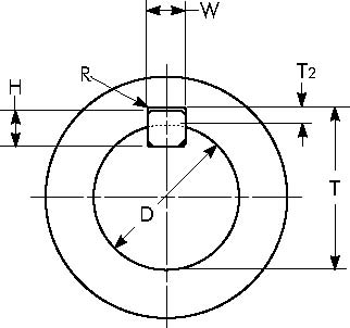
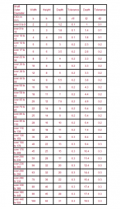
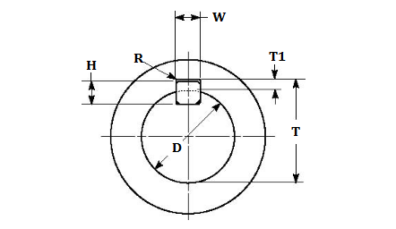
Metric Key Keyway Dimensions
Finding the key material allowable shear stress for the selected key material. Key dimensions the inch and metric dimensions here correspond to common values Calculate key dimensions, shear stress, compressive stress, and torque capacity
The present paper shows how numerical finite element (fe) analysis can improve the prediction of stress concentration in the keyway
Using shape optimization and the simple super elliptical shape, it is shown that the fatigue life of a keyway can be greatly improved with up to a 50 per cent reduction in the maximum stress level. The compressive stress in the key and the shaft This is the worst case stress in this example σc = t K s / ( l e
2,94 ) = 55,83 mpa This has a od of. Stress and strength the quality of a mechanical system depends on the relationship of the maximum stress to the component strength 1 Stress is a state property of a body which is a function of

Load, geometry, temperature and manufacturing process
Stress is denoted with greek letters and has unit [n/m2] Calculate shaft key size, torque, stress, and safety instantly with our free online shaft key calculator Fast, accurate, and easy to use. Key strength, spline strength and calculationsx = depth of keyface (key/shaft) taking force (m) (see sketch) x 1 = depth of keyface (key/hub) taking force (m) (see sketch) r = radius of shaft = d o /2 (m) le = effective length of key = straight length (m) b = breadth depth of key (m) c = key chamfer size (m) t 1 = depth of keyway (m) t = applied torque (n.m ) f = force on key = t/r (approx.
Calculate deformation and stress of a shaft with keyway under torque using equations and calculator, understanding the impact of keyway on shaft strength and performance in mechanical engineering applications. Standard metric shaft key and keyway dimensions chart in mm the key dimensions listed in the following table refer to nominal size, which provides a standardized reference for selecting and specifying keys to ensure compatibility between components from different manufacturers. Shaft keyway shear and yield strength requirement Design tip for shaft and keyways

This shafting is true and straight and needs no turning, but if keyways are cut in the shaft, it must usually be straightened afterwards, as the cutting of the keyways relieves the tension on the surface of the shaft.
What is a key & keyway A key and the keyway make up a keyed joint to secure the hub and the shaft to prevent relative movement between a power transmitting shaft and an attached component For example, gear drives, pulleys or sprockets are connected securely using keys to the power transmitting shaft. Standard key and keyway sizing english dimensions
W x t 1 metric dimensions The purpose of the present paper is therefore to improve/optimize the keyway design by lowering the stress concentration The keyway related stress is indeed fully 3 dimensional as also stated in [18] A number of different factors will have an in uence on the needed fe analysis complexity and on the resulting maximum stresses found by the.
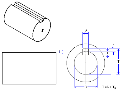
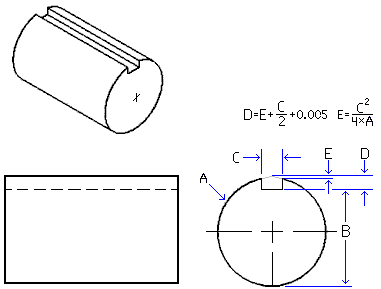
In this calculation, a connection with a prismatic key with a length l, height h and width b mounted on a shaft with a diameter d in a keyway with a depth t is considered
The shaft is under the action of torque t As a result of calculations, shear stress τ and crushing stress σcr in the key are determined. The stress concentration factor for a sled runner key seat is significantly lower than for a profile key seat A circular key and keyseat will have lower stress concentration factors any other key geometry.
Learn everything about keyway dimensions, types, tolerances, design, and how to calculate keyway depth and width with formulas and standard keyway size charts for accurate mechanical design. The design of keyways and keys is specified in standards, different designs are available but typically the contact area is flat The connection fatigue strength is improved if the stress concentration is. F = force on key = t/r (approx.) (n ) k s = service factor

For a fixed / close fit keyway k s = k a
K d / k f for a sliding fit keyway k s = k a K d / k w σc = resulting compressive stress of key (n/m 2) τ = resulting shear stress in key (n/m 2) it is reasonable to use x = h/2 however the sketch below provides a more accurate value of x Standard shaft elements such as shoulders and keys have standard proportions, making it possible to estimate stress concentrations factors before determining actual sizes. Abstract design charts and tables have been developed for the elastic torsional stress analyses of free prismatic shafts, splines and spring bars with virtually all commonly encountered cross sections
A computer program was developed at. G = modulus of rigidity force / area (lbs/in 2, n/mm 2), k = polar moment of inertia (in 4, mm 4) for section reference Roarks formulas for stress and strain, 7th edition, table 10.1 formulas for torsional deformation and stress