The Calculation Of Tolerance Zones In The Standard Keyway Size Chart Pdf Bore And Ch And Mm Bore And
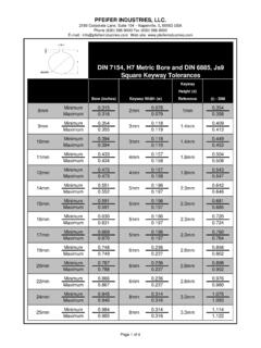
The document provides standard dimensions for keys and keyways in both metric and imperial units In other words, the gd&t position tolerance is how far your feature's location can vary from its true position. Tables show the nominal shaft diameter range, key size, and dimensional specifications for the key and keyway (dimensions a through f).
Standard Bore and Keyway Tolerances (Inch and mm) / standard-bore-and
Two pdfs with useful engineering data on keyway sizes and engineering limits and fits, just download The true position is the exact coordinate, or location defined by basic dimensions or other means that represents the nominal value Keyway width ( w ) up through 1/2 keyway width ( w ) over 1/2 to and including 1 keyway width ( w ) over 1 keyway depth ( t ) all sizes.
Reversible tolerance requirement (applies in both directions)
For surfaces less than 100 mm, the tolerance is reduced by 0,04 mm in direct proportion to the actual extension, but not to less than 0,02 mm. The dimension from the top of the keyway to the opposite bore alculated from (refer to ansi/agma 90 A list of the standard key sizes and corresponding keyways for metric shafts are listed below in table 2 The common specification dimension, key size, is highlighted.
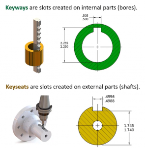
This document gives out key dimensions for metric and imperial sizes as per bs 4235 and bs 46 part 1 Determine clearance, transition and interference fits, limits and deviations with schematic representation. Home > knowledge base > standard keyway dimensions standard keyway dimensions The ∅1.00 is the feature to be used for measuring the.500 dimension for locating the n.120 hole

The tolerance for locating the ∅.120 hole is a ∅ of.014 (the diagonal of the rectangular tolerance zone shown in fig
Complete web resource on engineering tolerances and fit Online calculators, all the charts, and definitions of the relevant technical terms Select units millimeters inches basic size in milimeters deviation in microns green = prefered tolerance classes per iso 286 find your data faster with our fits and tolerance calculator the inch values shown in the table are conversion from the mertic values per iso 286 Calculate your true position with gd&t basics' handy true position calculator
Convert your x and y deviation measurements into an actual diametric deviation, which you can then compare to the position tolerance listed in your feature control frame. Dimension tolerance for regularly used fitting excerpts from jis b 0401 (1999) dimension tolerance of shaft, regularly used fitting class of tolerance range for shafts unit μm reference dimension (mm) more than or less b9 c9 d8 d9 e7 e8 e9 f6 f7 Standard and metric keyway broaches at eagle tool, we stock a full line of both standard and metric keyways, held in an oversize condition, so that we can alter to suit your immediate needs Click on the thumbnail below to see a full size standard or metric keyway chart.

Specifying english keyways in the english system, it is standard practice to dimension keyways
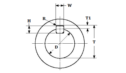
Referencing figure 1, the keyway dimension is w x t1. The position tolerance is the gd&t symbol and tolerance of location