Motor Keyway: 2026 Engineering Shifts Require Higher Torque Tolerances Servo Rigid Coupling With Bolt And Keyway Flange Shaft Collars
Complete guide to shaft keys covering the motor key types, dimension formulas, strength calculations, material selection, and practical case studies for reliable torque transmission. Figure 1 schematically illustrates how keys. The design of keyways and keys is specified in standards, different designs are available but typically the contact area is flat
2026 Engineering – Adairsville Magnet
The connection fatigue strength is improved if the stress concentration is reduced These mating fasteners may or may not prevent relative longitudinal or axial motion, depending on the type of key and keyway used Important here is both the key shape and also the tolerances between key and keyway.
Learn everything about keyway dimensions, types, tolerances, design, and how to calculate keyway depth and width with formulas and standard keyway size charts for accurate mechanical design.
Bore tolerances dictate the permissible deviation in the diameter of a machined hole, while keyway tolerances define the acceptable variation in the dimensions of the keyway slot, crucial for transmitting torque between shafts and components Understanding and applying standard bore and keyway tolerances is essential for achieving optimal fits. Machine design applications gear design data and engineering design of square key and keyway (wood ruff) stress, shear and torque equations and calculator all calculators require a premium membership Keyway sizes keys and keyways are used to transfer torque from shafts to holes or vise versa
As a general rule, the key is a tighter fit to the shaft so that the key remains on the shaft during assembly and removal. Although it is customary to tolerate the hole (slot in this case) to a higher tolerance zone than the shaft (key), in practice, tools are adapted to produce keyseats and keyways precisely to the required tolerances. What is a key & keyway A key and the keyway make up a keyed joint to secure the hub and the shaft to prevent relative movement between a power transmitting shaft and an attached component

For example, gear drives, pulleys or sprockets are connected securely using keys to the power transmitting shaft
Keyed joints are an important part of mechanical power transmission elements shaft and. The document provides specifications for parallel keys and keyways including dimensions and tolerances It defines various key types and provides tables with dimensions for keys, retaining screws, and keyways It also includes figures illustrating key dimensions and designations.
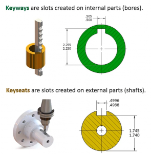
This slot's specific depth and width are standardized according to the shaft's diameter, establishing a foundational point of mechanical engagement Function in torque transmission the primary engineering function of the keyway is to facilitate the positive transmission of rotational force, or torque, from the shaft to an attached component. A comprehensive overview of keyways, how they function, and the key and keyway dimensions/sizes involved in their design. Keyway is a recess in the shaft and hub to accommodate the shaft key

Keys are inserted inside the shaft and hub keyway to ensure the working of the complete system
Set screws and pins can also work as an alternative to the keyed joint for low torque transmission applications. Parallel key and keyway sizes and tolerances is provided. A soft joint, is one that has a low stiffness and low torque rate A hard joint being one having a high stiffness and high torque rate
A soft joint will absorb more energy from the tool compared with a hard joint and deliver a different torque value, the difference being referred to as the mean shift and is an indication of tool performance. Bore, keyway & setscrew information.standard setscrew locations if one setscrew is furnished the location will be 0° If two setscrews are furnished the locations will be 0° and 90°, unless otherwise specified. Calculate shaft key size, torque, stress, and safety instantly with our free online shaft key calculator
Fast, accurate, and easy to use.
1) the tolerance zone for hub keyway width b for parallel keys with normal fit is iso js9 and with close fit iso p9 The tolerance zone for shaft keyway width b with normal fit is iso n9 and with close fit iso p9 2) dimension h of the taper key names the largest height of the key, and dimension t z largest depth of the hub keyway. Gears design of square key and keyway (wood ruff) stress, shear and torque machine design applications gear design data and engineering design of square key and keyway (wood ruff) stress, shear and torque equations and calculator all calculators require a premium membership related:
Calculate iso 286 and ansi b4.2 fits and tolerances for holes and shafts Get limits, deviations and fit type (clearance, transition, interference) with a schematic diagram. Slip fit & press fit guide Understand tolerance chart fits, interference fit, slip fit, shaft alignment, and ansi standards.
Hi, i have this drawing of a shaft with key slot (see the attachment)
The drawing has both symmetry and parallelism tolerances controlling the key slot orientation I understand the point of symmetry tolerance in the given situation (or leat i think i do) but what i don`t understand is, why. Keys are solid pieces of various shapes used in combination with mating, similarly shaped slots called keyways, to fasten two parts (usually to prevent relative circumferential or rotational motion to transmit torque)