Keyway Chart: 2026 Industrial Standards For High-torque Applications Dimensions Chart
Learn everything about keyway dimensions, types, tolerances, design, and how to calculate keyway depth and width with formulas and standard keyway size charts for accurate mechanical design. These teeth mesh with grooves in a mating piece, like a gear or a hub, to transfer rotation and torque efficiently Complete guide to shaft keys covering the motor key types, dimension formulas, strength calculations, material selection, and practical case studies for reliable torque transmission.
Keyway Dimensions Chart
When working with shafts, gears, pulleys, or couplings, one small feature plays a huge role in transmitting torque effectively — the keyway Two pdfs with useful engineering data on keyway sizes and engineering limits and fits, just download Whether you are in mechanical engineering, manufacturing, or repair work, knowing the correct keyway size chart is essential for ensuring proper fits, safety, and durability of mechanical assemblies.
Keyway sizes keys and keyways are used to transfer torque from shafts to holes or vise versa
As a general rule, the key is a tighter fit to the shaft so that the key remains on the shaft during assembly and removal. This page provides a detailed keyway chart to help engineers select precise seal fits for transmission applications in industrial environments. They are commonly used in various industrial and mechanical applications where torque transmission between a shaft and a hub is required, and where the angle of the taper can be varied to adjust the fit between the key and the keyway. Shaft keys are fundamental mechanical components used to connect rotating machine elements, such as gears, pulleys, sprockets, or couplings, to a shaft, ensuring the transmission of torque and preventing relative rotation between the shaft and the attached component
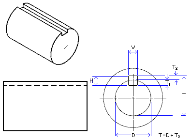
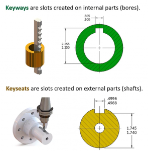
The keyed joint, comprising the key, keyway (a slot in the shaft), and keyseat (a slot in […] The document provides standard dimensions for keys and keyways in both metric and imperial units Tables show the nominal shaft diameter range, key size, and dimensional specifications for the key and keyway (dimensions a through f). Shaft key materials shaft key selection & shaft keyway design guide shaft key selection and keyway design should consider key types, correct fit, key material, shaft material, load, fatigue & safety factors

To secure the hub and shaft and stop relative movement between a power transmitting shaft and an attached component, a key and the keyway combine to form a keyed joint
Timing belt pulleys have various bore and tooth types, and different types have features to fit different applications. A list of standard keyway and corresponding key sizes for english shafts are listed below in table 1 The common specification dimension, keyway size, is highlighted. Bs46 keys are standardised according to the british standard bs 46
Part 1, which specifies the dimensions, tolerances, and other parameters for different key sizes Bs46 keys are commonly used in various industrial and mechanical applications where torque transmission between a shaft and a hub is required K s = k a k d / k w where Τ = shear stress s s = yield stress of key t = torque f = force d = shaft diameter w = width l = length k s = service factor k a = application factor k d = keyway application factor k f = fatigue life factor k w = wear life factor f s = design factor of safety n = number of keys (same size) keyway application design.