The Engineering Logic Of Angular Misalignment Handled By A Flex Coupling Shaft รูปภาพ เทคโนโลยี อุปกรณ์ อุตสาหกรรม เครื่องจักร แขน วิศวกรรม
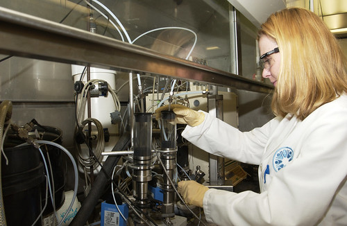
Pieces of rotating equipment are connected through a shaft coupling, every effort should be minimize coupling and shaft misalignment Designed to minimize vibration, our couplings enhance the lifespan and performance of your machinery. Proper alignment will reduce bearing, shaft and failures, bearing and coupling temperature, vibration, and energy consumption
Flexspan: Högskolan inte attraktiv arbetsplats för ingenjörer
In addition, will extend equipment life between planned maintenance intervals Our couplings can handle angular, parallel, and axial misalignments, ensuring smooth and efficient operation Abstract flexible disk couplings under misalignment generate restitution forces and moments that are introduced into the system, causing additional vibration
This work aims to perform a topology optimization with the solid isotropic material with penalization (simp) method, using the finite element method, on a circular disk coupling to achieve minimum restitution moment under angular.
Shaft misalignment and rotor unbalance are major concerns in rotating machineries Types of misalignment there are three variations to shaft misalignment Parallel offset (radial) misalignment, angular misalignment and a combination of angular and parallel offset Axial displacement is considered a form of misalignment dealt with by the coupling
Parallel (radial) misalignment occurs when the driving and driven shafts are parallel but with some offset between their axial. Consulting engineer for chemical engineering (www.che.com Suitable for applications where some degree of misalignment is expected, these couplings use a chain and sprocket mechanism to provide flexibility. In essence shaft misalignment has three components

Coupling for misaligned shafts introduction to shaft couplings shaft couplings play a pivotal role in mechanical engineering, allowing for the efficient transmission of power between two rotating shafts
This article delves into the intricacies of couplings designed specifically for misaligned shafts Types of misalignment misalignment in shafts can be categorized into angular, parallel, and. This alignment check should be done and if misaligned, corrected before grouting the baseplate and connecting to angular misalignment the pipework Flexible couplings should not be used to correct alignment problems, they can only take a limited amount of shaft misalignment
Misalignment can greatly shorten the life of the coupling flexible insert. There are three variations to shaft misalignment Axial displacement is considered a form of misalignment dealt with by the coupling. When two pieces of rotating equipment are connected through a shaft coupling, every effort should be made to minimize coupling and shaft misalignment

Proper alignment will reduce bearing, shaft and coupling failures, bearing and coupling temperature, vibration, and energy consumption.
Radial misalignment radial is the distance between the two shaft axis and is quantified by measuring the radial distance between the centerline of one shaft if it were to be extended to overlap the other Axial misalignment axial misalignment is the variation in axial distance between the shafts of the driving and driven machinery Angular misalignment angular misalignment is the effective. Angular misalignment refers to the condition when the shafts are not parallel, but are in the same plane with no offset
This is illustrated in figure 54.3 It is always necessary to take into account the size, geometry, or operating temperature of a given machine How much vibration and efficiency loss will result from the misalignment of shaft centers depends on shaft speed and coupling type Acceptable alignment tolerances are thus a function of shaft speed and coupling geometry.

Angular misalignment of shafts axial offset misalignment
Axial offset misalignment is the distance between the shaft centers of rotation measured at the plane of power transmission or coupling center There are four alignment parameters to be measured and corrected Vertical angularity, vertical offset, horizontal angularity, and horizontal. Discover the top 3 shaft coupling types—rigid, flexible, and universal joints
Learn how to install each like a pro to boost torque, reduce vibration, and cut downtime. A full gear coupling consists of two flexible hubs, each with external gear teeth, connected by a sleeve with internal teeth Torsional couplings are flexible couplings that offer a number of benefits to mechanical systems These couplings can protect your driveline and increase the life of downstream equipment by dampening vibration

Additionally, torsional couplings operate as flexible couplings by design
This feature helps them to compensate for radial, axial, and angular misalignment In the case of shaft alignment, rigid and flexible couplings can generally be used Although flexible couplings are preferable because they compensate for part of the misalignment, there are generally accepted standards for shaft misalignment with various types of coupling Premature bearing, seal, shaft or coupling failure.
Angular misalignment is produced when the center lines of the two equipment shafts the coupling connects are not parallel and they intersect at an angle Offset misalignment commonly called parallel offset, is when the two shaft centerlines are parallel and they do not intersect, they are offset by some distance.