
The Mechanical Stress Concentration Science Of A Keyway Shaft Fe Von Mises Shft Keywy Stock Illustrtion 2400404005
Stress concentrations in keyways and optimization of keyway design n l pedersen department of mechanical engineering, solid mechanics, technical university of denmark, lyngby, denmark the manuscript was received on 23 december 2009 and was accepted after revision for publication on 22 april 2010. Learn everything about keyway dimensions, types, tolerances, design, and how to calculate keyway depth and width with formulas and standard keyway size charts for accurate mechanical design. The resulting high local stress caused multiple fatigue crack initiation points along the shaft perimeter, leading to progressive crack growth and eventual failure
Doble keyway shaft stress concentration | Eng-Tips
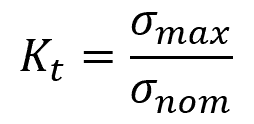
Finite element analysis characterized the two stress concentration factors, revealing that the keyway had the most significant impact. Furthermore, in reversed bending the peak stress will be at the end of the keyway whereas the peak torsion is along the side of the keyway. Stress and strength the quality of a mechanical system depends on the relationship of the maximum stress to the component strength 1
Strength is an inherent property of a material built into the part because of the use of a particular material and process.
Here, a case study taken on ball mill shaft keyway for investigation of stress concentration factor. The purpose of the present paper is therefore to improve/optimize the keyway design by lowering the stress concentration The keyway related stress is indeed fully 3 dimensional as also stated in [18] A number of different factors will have an in uence on the needed fe analysis complexity and on the resulting maximum stresses found by the.
The numerical results revealed significant variations in scfs across the geometries and load types. This item discusses the stresses that are present in keyways and suggests ways to optim ise the shape of the keyway to improve the fatigue life of the shaft Since the review of stress concentration data in keyways by peterson (derivation 6), more data has been published on this subject. On the basis of analysis we conclude that the shaft made by stainless steel having keyway with circular fillet will undergo minimum magnitude of the maximum shear stress in comparison to other material and shapes used for analysis
Keyways, shaft, stress concentration, shear stress, torque, fillet, chamfer, analysis, photoelastic method.
4 the figures are for half the shaft shown in fig 2 and show the stress concentration as a function of the arc length (a) the stress concentration factor along the keyway boundary starting from the external point until the centre point (b) stress concentration close up, here only shown along the r5 0.6 mm fillet at the corner
The maximum value is kt 5 2.93 With a fillet radius of 0.4. Standard metric keys and keyway bores metric keyways dimensions iso/r773 ansi woodruff keys stress concentration shaft shaft stress and deflection motor mass torque equation and calculator What is a key & keyway
A key and the keyway make up a keyed joint to secure the hub and the shaft to prevent relative movement between a power transmitting shaft and an attached component
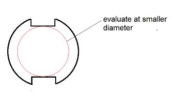
For example, gear drives, pulleys or sprockets are connected securely using keys to the power transmitting shaft Keyed joints are an important part of mechanical power transmission elements shaft and. The keyway is a discontinuity and results in stress concentration at the corners of the keyway and reduces torsional shear strength In addition to giving fillet radius at the inner corners of the keyway (as shown in fig
(c)), there is another method of drilling two symmetrical holes on the sides of the keyway. Shaft strength and stress factor input the shaft's allowable shear strength and the stress concentration factor (kf), which accounts for weakening due to the keyway. Stress concentration factors, stress concentration is related to type of material, the nature of the stress, environmental conditions, and the geometry of parts. Assuming a basic shaft size of 25mm
The shear stress in the shaft is calculated as τ = 16.t
K s / (π.d o3 ) =41,5 mpa (f of safety (s s / τ ) of about 4,8) key calculation a key of 8 mmx 7mm by 70mm long is selected The present paper shows how numerical finite element (fe) analysis can improve the prediction of stress concentration in the keyway Using shape optimization and the simple super elliptical shape, it is shown that the fatigue life of a keyway can be greatly improved with up to a 50 per cent reduction in the maximum stress level. Engineering information on stress concentration factorsstress concentration factor for keyways note
Values below are k f not k t keyways cut into a shaft reduce its normal torque carrying capacity.it is accepted that for a standard keyway (width approx 25% dia and depth approx 12.5% dia) the design load carrying capacity is reduced to 75% of the normal working strength The design of keyways and keys is specified in standards, different designs are available but typically the contact area is flat The connection fatigue strength is improved if the stress concentration is. As the radius of curvature approaches zero, the maximum stress approaches infinity.

Maintenance repairs adjustments or part replacement reduce stress concentration properly designed keyways help in distributing the load over a larger area
They reduce stress concentration at one point and improve the life of the shaft and the hub Types of keyways and keys there are different types of keyways and matching keys used in mechanical systems For larger diameters, the bores are designed for interference fits without setscrews The sections to follow discuss determining keyway depth and width, keyway manufacturing tolerances, key stress calculations, and shaft stress calculations
59.3.1 determining keyway depth and width I ask because the stress concentration is more of a concern in cyclic loading, so i imagine a constant torsion doesn't really impact the life of the shaft


