Designers Debate The Torsional Strength Of The Keyway Shaft With Torque Applied Deformation And Stress Equations And
The design of keyways and keys is specified in standards, different designs are available but typically the contact area is flat We also have an imperial keyway calculator. The connection fatigue strength is improved if the stress concentration is.
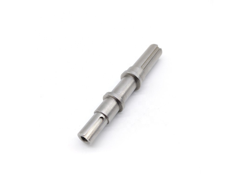
High Precision Keyway Motor Shaft, Precision Shaft Company -Atlas
To determine the torque capacity of key. In the field of design n l pedersen [1] work on effect of stress concentration and optimization of keyway design using numerical finite element analysis for the prediction of stress concentration in the keyway. The stress in the hub need only be considered if the hub material design strength is significantly lower than the shaft or key strength
Based on shear based on compressive strength iso straight sided spline capacity notes
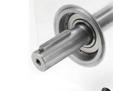
Tables of the various factors and design strengths are found on. A standard ball bearing is to be placed on diameter d2 and this surface is machined to form a good seat fro the bearing. Calculate deformation and stress of a shaft with keyway under torque using equations and calculator, understanding the impact of keyway on shaft strength and performance in mechanical engineering applications. Shaft key selection and keyway design should consider key types, correct fit, key material, shaft material, load, fatigue & safety factors
To secure the hub and shaft and stop relative movement between a power transmitting shaft and an attached component, a key and the keyway combine to form a keyed joint. Shaft keyway shear and yield strength requirement Design tip for shaft and keyways This shafting is true and straight and needs no turning, but if keyways are cut in the shaft, it must usually be straightened afterwards, as the cutting of the keyways relieves the tension on the surface of the shaft.

Optimizing the key dimensions to satisfy strength requirements while minimizing size and cost
The final key design should transmit the required torque safely while minimizing stress concentrations on the shaft. Complete guide to shaft keys covering the motor key types, dimension formulas, strength calculations, material selection, and practical case studies for reliable torque transmission. In other words, the torsional strength of the shaft is reduced. The maximum shear stress in the key and the maximum torsional shear stress in the shaft can be derived from the yield strength of the shaft material
We also have an metric keyway calculator. The elastic stress analysis of uniformly circular shafts in torsion is a familiar and straightforward concept to design engineers As the bar is twisted, plane sections remain plane, radii remain straight, and each section rotates about the longitudinal axis. The objective is to calculate the shaft size having the strength and rigidity required to transmit an applied torque

The strength in torsion, of shafts made of ductile materials are usually calculated on the basis of the maximum shear theory.
In this discussion, a shaft is defined as a rotating member, usually circular, which is used to transmit power Although normal and shear stresses due to torsion and bending are the usual design case, axial loading may also be present and contribute to both normal and shear stresses The design case must consider combined stresses. Material is selected and the allowable stresses are found accounting for all the factors that affect the strength of the part
The dimensions of the part, required by the design criteria (strength, rigidity, wear resistance etc.) corresponding to the accepted design scheme, are determined; Key strength, spline strength and calculationsx = depth of keyface (key/shaft) taking force (m) (see sketch) x 1 = depth of keyface (key/hub) taking force (m) (see sketch) r = radius of shaft = d o /2 (m) le = effective length of key = straight length (m) b = breadth depth of key (m) c = key chamfer size (m) t 1 = depth of keyway (m) t = applied torque (n.m ) f = force on key = t/r (approx. The purpose of the present paper is therefore to improve/optimize the keyway design by lowering the stress concentration The keyway related stress is indeed fully 3 dimensional as also stated in [18]

A number of different factors will have an in uence on the needed fe analysis complexity and on the resulting maximum stresses found by the.
The shear stress due to the torsion will be greatest the bending on outer moments surfaces On a shaft can be determined by shear and bending moment the diagrams Bending since moments most shaft on problems a shaft can incorporate be determined gears or by pulleys shear that and introduce bending forces moment diagrams To accommodate the key into the shaft a slot is cut into the shaft which is known as the keyway