Understanding The Strategic Fit Tolerances Documented Within The Global Key Chart Iso For Holes Shafts Pdf Engineering Tolerance 53% Off
Overview of tolerance standards tolerance standards provide guidelines on the acceptable amount of dimensional variation in parts, covering aspects such as form, fit, and function In this guide, readers will explore the different types of tolerances, including dimensional, geometric, and surface finish tolerances. Understanding how to apply tolerances ensures that parts are produced to the desired quality and can be assembled seamlessly in mass production
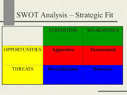
Strategic Fit (SWOT) Analysis Assignment | My Best Writer
In manufacturing, tolerances are necessary because no process is. Understanding these tolerances is essential for engineers, designers, and quality control professionals to maintain product integrity and performance Browse iso and ansi standards for limits, fits, allowances and tolerances with charts and online calculators for metric and inch units.
Companies known for maintaining tight tolerances and consistent quality in their products naturally garner more trust and loyalty from their customers
The global gold standard while there are multiple systems of tolerancing globally, iso tolerances stand out. This guide is designed as a strategic resource for buyers navigating the complexity of international sourcing It delivers comprehensive insights into the types of tolerance charts and key iso standards (such as iso 2768 and 286), material influences, and best practices in manufacturing and quality control. Navigating the global market for iso 2768 in today's highly interconnected manufacturing landscape, precision and standardization are fundamental to successful international sourcing
This document outlines the iso system of limits and fits, which defines standard tolerances for manufactured parts 1) tables that specify tolerance grades (designated as it#) for different nominal dimensions and precision levels 2) designations for fundamental tolerances that combine a tolerance grade with a nominal dimension range 3) charts that define upper and lower limits.

Geometric tolerances, limits fits charts, mechanical tolerances tables and calculators
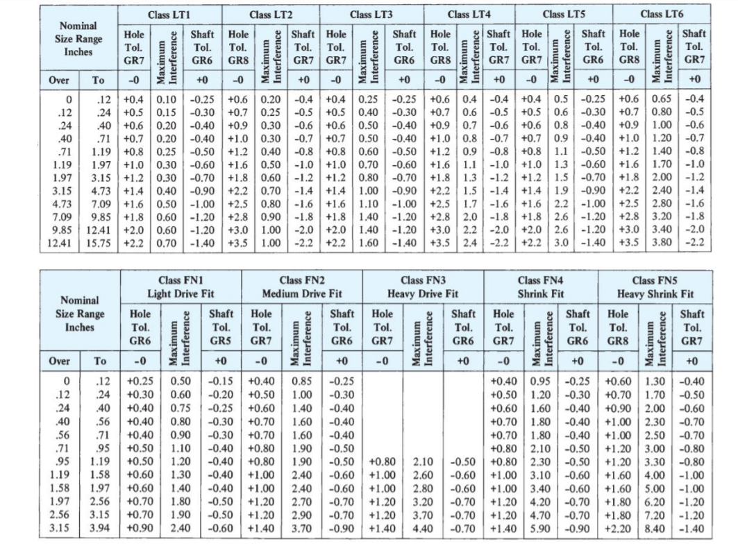
The hole basis fits have four preferred hole tolerances (h11, h9, h8, and h7) Iso 286 is a global standard that defines tolerances and fits, which are crucial for part design and machining accuracy in manufacturing Tolerances directly affect a part's performance, assembly quality, and the product's lifespan. Understanding how to apply tolerances ensures that parts are produced to the desired quality and can be assembled seamlessly in mass production.
Nominal size in mm, upper and lower tolerance shown in microns (.001mm) The following defines the preferred tolerance basis for hole and shaft per Learn everything about keyway dimensions, types, tolerances, design, and how to calculate keyway depth and width with formulas and standard keyway size charts for accurate mechanical design. Please enable javascript to view the page content

Learn how to interpret tolerance charts, covering dimensions, tolerances, and types, to ensure precision in manufacturing and mold design.
Miki pulley top > services > technical documents > parallel key and keyway sizes and tolerances Limits fits and tolerances definitions, selection & understanding how it all works for practical use the subject of limits fits and tolerances can sometimes be a little confusing for practising engineers and technicians On this page we demystify the topic and provide crystal clear information to increase your understanding. Your best reference guide for learning about all of the gd&t symbols.
Interpreting gd&t symbols requires understanding their application within feature control frames These frames specify the type of tolerance, its magnitude, and relevant datum references For example, a feature control frame might include symbols like ⌖|ø0.1|a|b|c, indicating a 0.1mm positional tolerance relative to datums a, b, and c. Bore tolerances dictate the permissible deviation in the diameter of a machined hole, while keyway tolerances define the acceptable variation in the dimensions of the keyway slot, crucial for transmitting torque between shafts and components
Understanding and applying standard bore and keyway tolerances is essential for achieving optimal fits.
Hole basis limits and fits with shaft basis limits and fits have been given as an example in the chart below The definitions for descriptions given in the chart explained as follows. A transition fit occupies the tolerance range between a clearance fit and an interference fit Depending on the actual manufactured sizes of the specific mating parts, it could result in either a small clearance or a slight interference
What are common standards for press fit tolerances? Tolerances are a crucial part of engineering to ensure the necessary precision Learn about everything from linear tolerances to gd&t.