Understanding The Material Logic Behind The Long-life Strategy Of Each Leeson Motor Wiring Diagram Electric Wiring Draw
Leeson makes energy efficient electric motors for various applications The wiring diagram includes labels and symbols that indicate the different components and connections of the motor. Find technical documentation and technical manuals for our motors and products here.
Wiring Diagram Leeson Electric Motor - Wiring Draw
Electric motors engineered for performance and reliability for commercial & industrial applications This diagram provides information on how to properly wire the motor for various applications Explore ac, dc, ec, and gearmotor solutions.
By understanding the differences between ac and dc motors, employing effective troubleshooting techniques, and selecting the appropriate motor for the application, you can ensure optimal performance.
This comprehensive product bulletin by leeson electric provides detailed specifications, performance features, and selection guides for all stainless steel motors, gearmotors, and adjustable speed drives The leeson motor, a vital component in various industrial applications, plays a significant role in china's rapidly evolving manufacturing landscape As industries increasingly rely on efficient and reliable motors, understanding the intricacies of leeson motors becomes essential for engineers, technicians, and business owners alike. Leeson right angle and parallel shaft gearmotors are offered in both ac and dc designs
These industrial strength gearmotors are designed for reliability and long life in the toughest applications. All are built for rugged commercial and industrial applications Whether you're an engineer, a technician, or simply someone interested in the workings of electric motors, understanding how leeson motors operates and the products they offer can be quite beneficial. What do the symbols and markings on leeson motors wiring diagrams represent?
What are the potential consequences of misinterpreting leeson motors wiring diagrams?
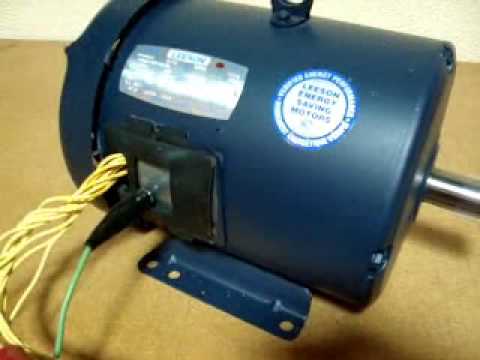
A leeson motor wiring schematic is a diagram that shows the connection between the different components of a leeson electric motor This schematic is a valuable tool for electricians and technicians who need to troubleshoot or repair leeson motors It provides a clear and detailed illustration of how the motor is wired, including the connections for power supply, start and run capacitors, and. Leeson motors can be found on material handling equipment, pumps, fans and blowers, machine tools, power transmission products, agricultural applications, treadmills, food processing equipment, data processing, medical, textile, packaging, graphic arts, woodworking, and a host of other industrial and commercial products.
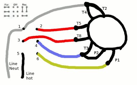
The leeson motor wiring diagram can help you better understand how to connect your motor to your power source Understanding the wiring diagram is essential in order to connect the motor correctly and safely. Leeson 5 hp motor single phase wiring diagram The ultimate guide to understanding your motor's wiring when it comes to understanding the wiring of your leeson 5 hp motor, things can get a bit confusing.
Leeson motors wiring diagramsunderstanding leeson motors wiring diagrams when it comes to maintaining or repairing an industrial motor, wiring diagrams are an essential tool
Knowing how to read and interpret these diagrams is required for troubleshooting and repairs Leeson motors offers a comprehensive range of wiring diagrams for customers to view that can help in the repair process The following topics related to the wiring diagrams for this type of motor will be discussed in detail Explore logic's definitions from aristotle to modern thinkers like stebbing
Understand reasoning, arguments, and its role in critical thinking. Learn more about ideal motor conditions, today. The leeson single phase motor wiring diagram is a crucial element in understanding how to properly connect and wire a single phase motor This diagram provides a visual representation of the electrical connections and components involved in the motor's operation.
Programmable logic controllers (plc) are often defined as miniature industrial computers that contain hardware and software used to perform control functions
More specifically, a plc would be used for the automation of industrial electromechanical processes, such as control of machinery on factory assembly lines, amusement rides, or food. The proper selection and application of electric motors and related products and components, including the related area of product safety, is the responsibility of the customer Operating and performance requirements and potential associated issues will vary appreciably depending upon the use and application of such products and components The scope of the technical and application.
Leeson three phase motor wiring diagrams are essential to understanding and troubleshooting electrical systems Whether you're an electrician, an engineer, or a technician working on commercial and industrial machinery, these schematics provide the necessary information to correctly wire the motor. Study with quizlet and memorize flashcards containing terms like _____ is a continuous value i.e 0 or 5 volts, frequently used transducer outputs are and more.

Access comprehensive technical information and resources for leeson products, including manuals, guides, and support to optimize your motor applications.
The leeson c184k17db31a wiring diagram is a visual representation of the wiring connections for the leeson c184k17db31a motor